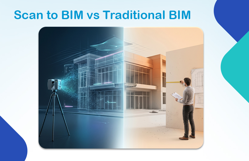
Choosing between Scan to BIM vs Traditional BIM isn’t just a technical decision; it directly impacts your project’s cost, timeline, and accuracy.
If you’re working on an existing building, one method clearly outperforms the other.
If you’re starting from scratch, the answer changes completely.
This guide breaks it down clearly so you can choose the right approach with confidence.
Scan to BIM vs Traditional BIM – Which is Better?
- Scan-to-BIM is better for existing buildings because it captures real-world conditions with high accuracy.
- Traditional BIM is better for new construction because it is faster and more cost-effective.
The best method depends entirely on your project type, accuracy requirements, and budget.
What is Scan-to-BIM?
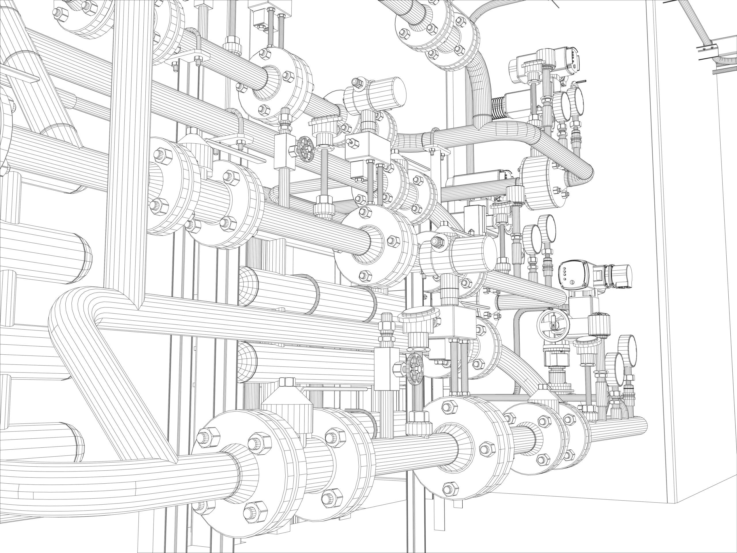
Scan-to-BIM is a process where real-world buildings are captured using LiDAR (laser scanning) or photogrammetry and converted into a BIM model.
It creates an as-built model based on actual site conditions not assumptions.
How Scan-to-BIM Works:
- Laser scanners capture millions of data points
- A point cloud is generated
- BIM experts convert it into a 3D model (Revit, Navisworks)
Key Technologies:
- LiDAR scanning
- 3D laser scanners (FARO, Leica)
- Photogrammetry
- Point cloud processing software
Best Use Cases:
- Renovation & retrofit projects
- Heritage documentation
- Facility management
- Complex structures
Key Benefit:
Millimetre-level accuracy with real-world data

What is Traditional BIM Modelling?
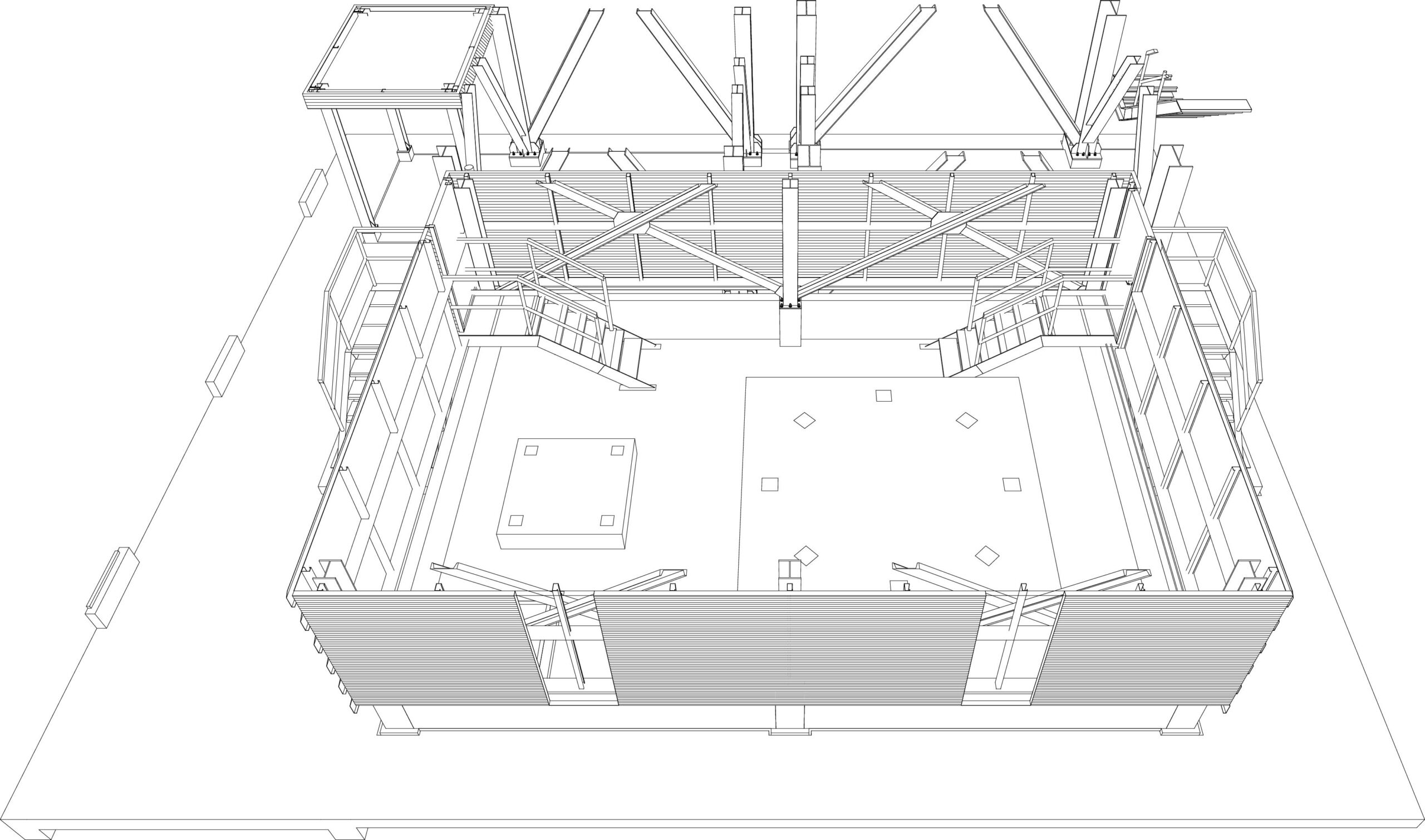
Traditional BIM modelling creates a digital building model using design drawings, plans, and specifications.
It represents design intent, not actual site conditions.
How It Works:
- 2D drawings (plans, sections, elevations) are created
- BIM tools (like Revit) convert them into 3D models
- Data (materials, dimensions, systems) is added
Best Use Cases:
- New construction projects
- Residential & commercial buildings
- Early-stage design coordination
Key Benefit:
Faster and lower-cost project start

Scan to BIM vs Traditional BIM
| Criteria | Scan-to-BIM | Traditional BIM |
|---|---|---|
| Input Data | Point cloud (LiDAR) | 2D drawings |
| Accuracy | Very high (as-built) | Depends on drawings |
| Best For | Renovation, retrofit | New construction |
| Cost | Higher upfront | Lower initial cost |
| Risk | Very low | Moderate |
| Output | As-built model | Design model |

Cost Comparison – Which is More Affordable?
Scan-to-BIM Costs:
- Laser scanning services
- Equipment & site access
- Point cloud processing
- LOD (Level of Detail) requirements
Higher upfront cost, but reduces rework and costly errors
Traditional BIM Costs:
- Drafting & modelling
- Design coordination
- Revision cycles
Lower initial cost, but can lead to hidden costs during construction
Key Insight:
Scan-to-BIM often delivers better ROI in complex or renovation projects.
Accuracy Comparison – The Biggest Difference
Accuracy is where the gap becomes obvious.
Scan-to-BIM:
- Captures real-world geometry
- Detects irregularities & misalignments
- Reduces clashes significantly
Traditional BIM:
- Based on assumptions
- Depends on drawing quality
- May miss site deviations
Is scan-to-BIM more accurate than traditional BIM?
Yes, scan-to-BIM is generally more accurate than traditional BIM, especially for existing buildings.
Scan-to-BIM uses laser scanning (LiDAR) or photogrammetry to capture real-world conditions with millimetre-level precision. This means the resulting BIM model reflects the actual structure, including irregularities, misalignments, and hidden deviations.
In contrast, traditional BIM relies on design drawings and manual measurements. Its accuracy depends on how precise and up to date those drawings are, which can lead to gaps between the model and real-world conditions.
Verdict:
Scan-to-BIM is the clear winner for accuracy.
When to Choose Scan-to-BIM
Choose this method if:
- You’re working on existing buildings
- Accuracy is critical
- The structure is complex
- You need as-built documentation
Example Projects:
- Hospital renovations
- Airport upgrades
- Heritage restoration
When to Choose Traditional BIM
Choose this method if:
- You’re building from scratch
- You already have design drawings
- Budget is limited
- Speed is important
Example Projects:
- Residential developments
- Commercial buildings
- Industrial plants
Common Mistakes to Avoid
Most project teams choose the wrong method because they:
- Use traditional BIM for renovation projects
- Skip scanning to save upfront cost
- Ignore hidden structural deviations
- Underestimate rework costs
These mistakes often lead to delays, budget overruns, and clashes.
Real-World Insight
In renovation projects, Scan-to-BIM can reduce rework by up to 25–30% by eliminating unknown site conditions.
That’s where it becomes a strategic investment not just a technical upgrade.
Conclusion
The choice between Scan to BIM vs Traditional BIM ultimately depends on your project requirements:
- Existing building or renovation? → Scan-to-BIM is the right choice
- New construction project? → Traditional BIM is more efficient
There is no universally “better” method – only the right approach based on accuracy needs, budget, and project stage.
Partnering with the right BIM expert can make this decision easier and ensure your project runs smoothly from start to finish.
At Monarch Innovation, we help clients choose and implement the most effective BIM workflow, whether it’s high-precision scan-to-BIM for existing structures or efficient traditional BIM for new developments. Our focus is on delivering the right balance of accuracy, cost, and speed for every project.
Need Expert Guidance?
If you’re planning a project and unsure which BIM approach is right for you, connect with the team at Monarch Innovation for expert consultation and tailored BIM solutions.
FAQs
How long does a scan-to-BIM project take?
From a few days to several weeks depending on building size and LOD.
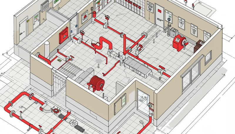
Can scan-to-BIM capture MEP systems?
Yes, laser scanning captures ducts, pipes, and electrical systems with high precision.
What LOD is used in scan-to-BIM?
Typically, LOD 300–400, depending on project needs.