Construction drawings are used for a wide variety of reasons and applications in construction and architectural projects and activities.
What is a construction drawing?
It is a graphical representation of what will be built, how it will be laid out, the components, framework, and dimensions. There is a construction drawing highlighting the details of every aspect of a construction project.
Construction Drawings including each of its subtypes are helpful to different groups of workforce assigned with doing or overlooking the various tasks that make up a construction project.
How are construction drawings made?
Rarely are construction plans drawn by hand anymore. They are either sketched and rendered using computer-aided drafting such as computer-aided design (CAD) software. And in recent times, Building Information Modeling (BIM) software has made it easy to render and visualize in detail the virtual construction models (VCM).
To know more about BIM services, budgeting, and how they can benefit your project, reach out to us at Monarch Innovation for all queries, assistance, and collaborations.
Top most common types of Construction drawings used regularly in construction industries.
Architectural Drawings
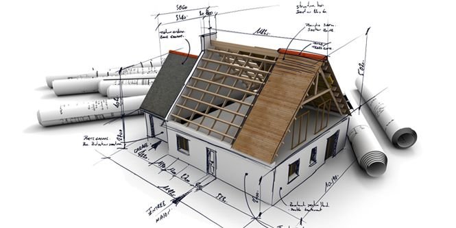
Architectural Drawings are drawing work that is used in building drawings to depict the dimensions, depth, and layout of the actual building, before beginning the construction. Architectural Drawings act as a blueprint construction, drawn to scale, to help the engineers visualize the project.
Various types of Architectural Drawings commonly used are:
1. Block Plan
This drawing gives a layout of the site or the buildings in the surrounding area, laid out on a map drawn to scale.
- It gives a firsthand idea of the roads, boundaries, and other such details that are necessary to understand where your construction site lies.
- It helps the person dealing with your construction plan or project request to understand what and where you are proposing it and help you out with it too.
- Block plans are made in relation to Ordnance Survey Maps and the recommended scales used are 1:2500, 1:1250, or 1:500.

2. Foundation plan
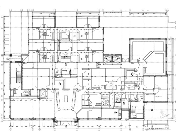
Not to be mistaken for just the ground or basement floor plan. Foundation Plans are drawing work to render any of the floors of the building being constructed. They help visualize the dimensions, size, shape, height, and configuration of rooms/stairs/landings with each other.

3. Floor plans
In-depth rendering of the layout of the rooms for each floor. It describes in 2D the orientation of rooms and components to each other. Floor plans may or may not be utilized in commercial or non-commercial building projects, but it is necessarily still made as part of the drawing work.

4. Sectional Drawings
These are drawings that depict a part or whole of the framework in sliced form. It helps understand the measurements of various building components with each other, the materials used in the construction of those components, the height, depth, and hollowness, etc.

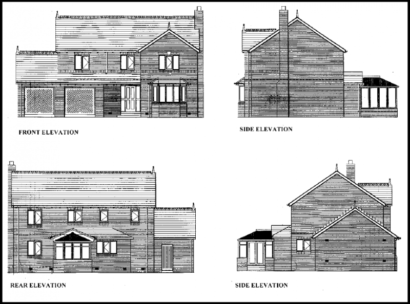
5. Elevation Drawings
These architectural drawings offer an aesthetic overview of the various components of the building such as columns, windows, and doorframes. It also helps understand the relative surface, internal markings, and relative height of these different components to each other.
6. Site Plan
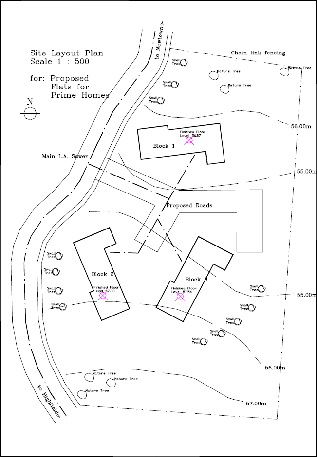
A site plan is a detailed drawing that shows the entire construction site with property boundaries, existing structures, proposed new building locations, site grading/topography, and other site features like landscaping, parking areas, utilities, etc.
7. Isometric Drawing
An isometric drawing is a type of 3D parallel projection used to represent objects pictorially. It shows three sides of an object with the vertical lines projecting at a 30-degree angle and the horizontal lines projecting at a 30-degree angle.
8. Axonometric Drawings
Axonometric drawings are types of 3D parallel projections that show an object in an oblique/angled view. They include isometric, dimetric, and trimetric drawings depending on the exact angle used for the horizontal and vertical lines.
9. Presentation Drawings
Presentation drawings are highly detailed renderings or 3D models used to communicate and visualize the design intent for clients, stakeholders, and approving authorities. They showcase the appearance, materials, and aesthetic qualities of the project.
10. Survey Drawings
Survey drawings represent the existing conditions on a construction site based on detailed field survey data. They show site topography, boundaries, existing structures, underground utilities, and other existing features crucial for planning new construction.
11. Location Drawings
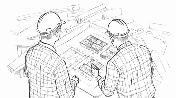
Location drawings are used to indicate the specific position or location of building components, systems like HVAC ducts, plumbing pipes, electrical conduits, etc. within the overall construction. They help avoid conflicts during installation.
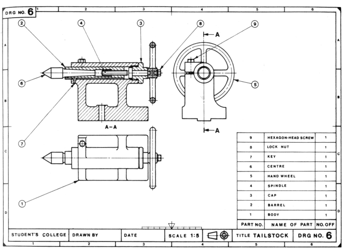
12. Assembly Drawings
Assembly drawings illustrate in detail how different components and materials fit together during construction. They provide crucial information on the sequence, connections, and relationships between various building parts to guide proper assembly.
13. Parametric Drawing
A parametric drawing is created using parametric modeling software that allows the drawing views to automatically update when design parameters like dimensions or specifications are changed. This ensures consistent, coordinated drawings across all sheets.
14. Design Drawing
Design drawings are conceptual drawings that architects create early in the design process to explore, develop, and communicate design ideas and concepts to clients before moving to more detailed stages. They convey the building’s overall form, mass, and character.
15. Reflected Ceiling Plan
A reflected ceiling plan is a drawing that shows the layout of the ceiling as if it’s viewed from above by someone standing in the room looking upwards. It depicts ceiling-mounted elements like light fixtures, diffusers, speakers, etc.
16. Record / As-built Drawings
Record drawings, also called as-built drawings, are the final set of drawings updated to incorporate all the construction changes, modifications, and as-built conditions from the actual construction process. They document the constructed project accurately.
Structural Drawings

Structural Drawings also serve as civil engineering drawings. They are useful in understanding the physical nitty-gritty of a building framework. They act as a structural design guide for the workers and on-site engineers. Common types of structural drawings are:
17. General Note
An overview of all the codes, procedures, abbreviations, etc required to give a comprehensive guide to getting to work on the construction site. This includes concrete mix, details for other structural drawings, lengths and construction types of each component, etc.
18. Excavation Drawing
This civil engineering drawing describes the dimensions and positions for the excavation process prior to the actual building work. It covers details like tunneling, shafts, removal of soil, grid plans, etc. required to start the groundwork.
19. Column Layouts
These structural drawings include the layouts of the way columns will be laid out. It makes it easier for contractors to plan the layout of the building and start the process by identifying the position and distance between columns across the floor.
20. Beam Layouts
It includes all the beam-like structures, such as the ones supporting the roof and the windows, or the beams used for strengthening purposes. They are designed for each floor and cover the length, height, material, etc.
21. Roof slab layouts
this civil engineering drawing describes the exact dimensions of all the slabs required for roofs or slants. It can be designed over AutoCAD software as it requires precision and data.
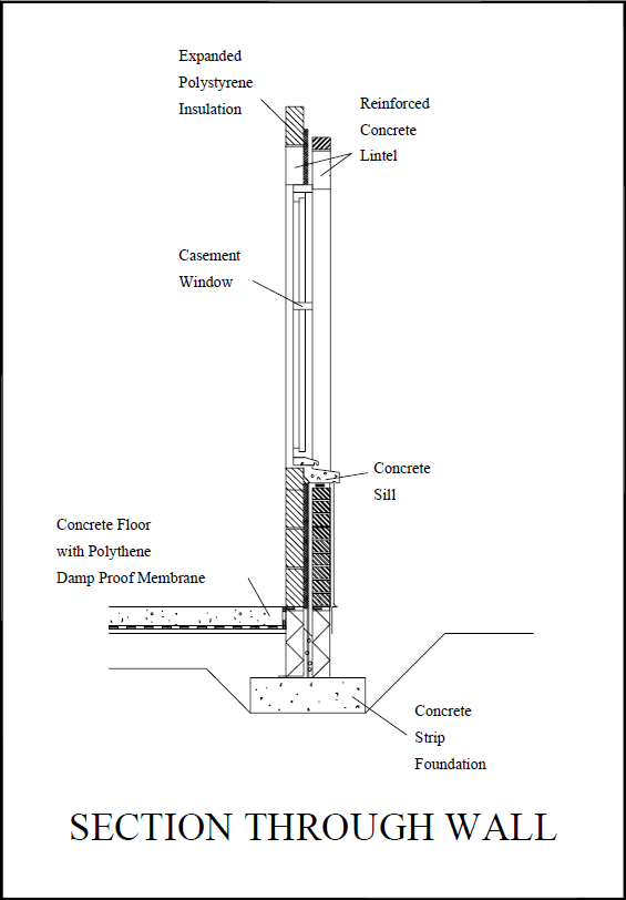
22. Section Plan
A section plan is a drawing that shows a cross-sectional vertical or horizontal view through the building by cutting through it. Section plans clarify the internal construction, framing, and relationships between different structural elements.
23. Detail Drawings
Detail drawings are large-scale drawings focused on specific construction details and connections between different structural components. They provide in-depth, magnified information crucial for installation and assembly by showing reinforcements, fasteners, dimensions, etc.
24. Component Drawing
Component drawings focus on providing comprehensive details and dimensions of individual structural elements like beams, columns, footings, etc. They serve as a reference for manufacturing, fabrication, or on-site construction of these components.
25. Column Layout
A column layout plan indicates the locations of all structural columns in the building along with the column gridlines and dimensions. It helps ensure proper positioning and installation of columns during construction.
26. Plinth Beam Layout
The plinth beam layout plan shows the layout, positions and dimensions of all plinth beams or grade beams that will be constructed below and support the load-bearing walls at the foundation level.
27. Lintel Beam Layout
A lintel beam layout plan depicts the locations, sizes, and geometry of all lintel beams provided over wall openings like doors, windows, etc. to transfer loads across those openings safely.
28. Roof Beam Layout / Shuttering
The roof beam layout plan shows the framing layout for supporting the roof structure with dimensions for beam sizes and spacing. The shuttering layout indicates formwork patterns/positioning for concrete roofs.
29. Framing Plan
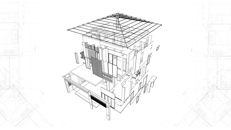
A framing plan is a structural drawing that illustrates all the load-bearing, framed elements in the building like floors, walls, and roofs. It clarifies the overall framing system, member sizes, connections, and relationships.
30. Engineering Drawing
An engineering drawing is a technical drawing produced by structural engineers with precise dimensions, calculations, and specifications related to the building’s structural design, analysis, and detailing following relevant engineering codes.

31. Installation Drawings
Installation drawings provide clear instructions and details guiding the installation processes for prefabricated structural components or building systems manufactured off-site for easy assembly on the construction site as per design specifications.
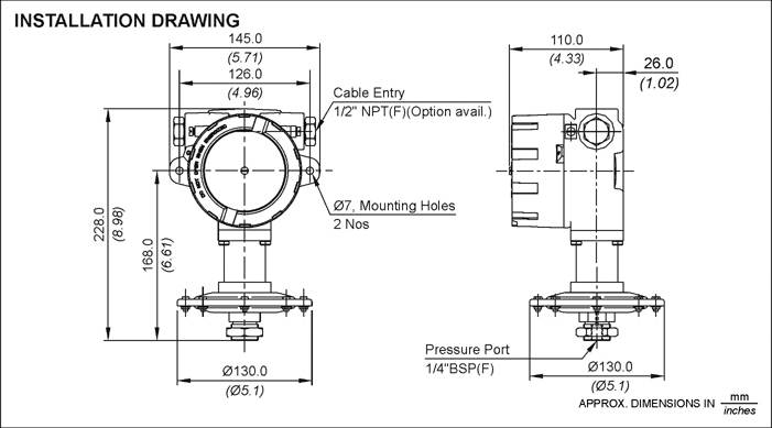 Installation Drawing https://www.designingbuildings.co.uk/
MEP Drawings
32. Electrical drawings
Most residential construction drawings or commercial construction drawings require a functional outline of the number of power outlets, light fixtures, fan fixtures, etc. They also include the wiring pattern and details about the electrical load it can carry. Common details included in Electrical Drawings are:
- Earthing layout
- Light fixture layout
- Generator and other equipment
- Cable tray layout
- Hazardous area classifications
- Lighting protection system

Just like electrical layouts, plumbing is another part of any residential or commercial construction drawing that marks the points where plumbing components need to be set up. Space is left here accordingly for further pipe and sanitary ware fixtures to be added once the structural component is finished. Plumbing drawings commonly include:
- Pipes – water pipes, drainage pipes, internal pipes
- Material of pipes
- Outlet points – taps, sinks, tanks etc
- Position and location of pipes and outlets
33. HVAC/Mechanical Drawings
These are known as mechanical construction drawings. They provide details and a design framework for heating and ventilation systems in a building. Central heating/cooling, air conditioning vents, ventilators, etc are all included according to the need and site of the building plans. Builders use these design constructs in their process accordingly.
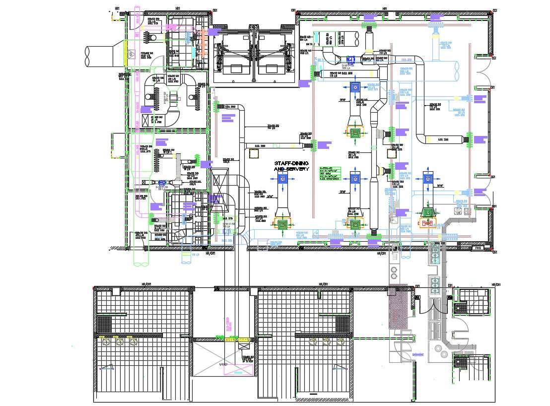
34. Piping Spool Drawings
Piping spool drawings are detailed drawings focused on specific prefabricated sections of pipes called spools used in industrial piping systems. They show precise dimensions, connections, and routing of these spool sections.
35. Firefighting Drawings
In today’s construction systems, safety design is paramount. Firefight Drawings are also a part of blueprint drawings of a building that allocate points for fire hoses, fire escapes, water outlets, sandbags, or any other fire safety equipment required by the regulatory body overseeing the project.
Additional Drawing Types
36. Production Drawings
These Construction Drawings are used to convey functional information to the workers and engineers on site. It describes the materials, the assembly of various parts, the tools required, the dimensions, and other information required during the process. It may also include additional information or an infographic on how to meet those set requirements.
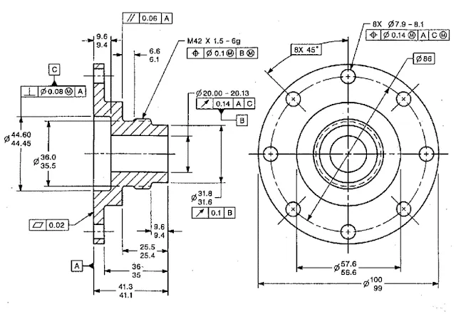
37. Environmental Plans
Making sure environmental guidelines and management are properly followed is a part of construction projects that cannot be overlooked. The aim is to minimize environmental damage and future negative impacts of the construction project. It includes measures like:
- Chemical disposal mechanisms
- Management of erosion and sedimentation
- Outlining environmental guideline compliance measures
- Measures to handle accidents and emergencies like fire
38. Finishing Drawings
These include finer and more detailed plans of the building after the whole structural and architectural framework has been set up. These are required for the aesthetic and functional value of the building. These construction drawings include details of:
- Tile patterns,
- Floor patterns
- False ceilings
- Paint colors and textures
- Plaster
- Woodwork
- Motifs and designs
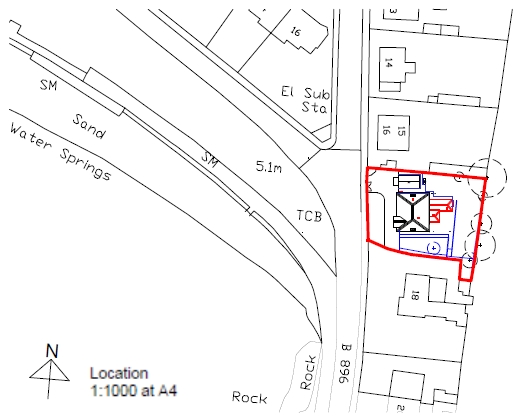
39. Location Plan
A location plan is a simple drawing that shows the location of the construction project site about its surroundings like nearby roads, landmarks, neighborhoods etc. to help identify and access the site easily.
40. Shop Drawings / Fabrication Drawings
Shop drawings or fabrication drawings provide precise dimensions, details, and instructions from the manufacturers/suppliers for prefabricated construction components, materials, or equipment off-site before delivery to the construction site for installation.
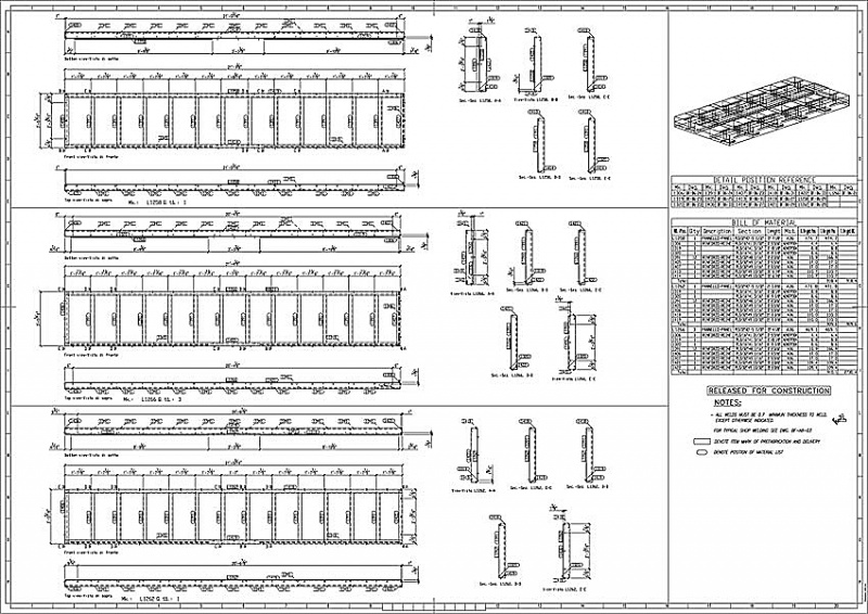
41. Scale Drawings
Scale drawings refer to any plans, sections, elevations, or detail drawings that are produced using precise measurement scales to represent actual dimensions accurately, allowing dimensions to be determined from the drawings reliably.
42. Perspective Drawings
Perspective drawings are three-dimensional views or illustrations drawn to show depth and provide a view of the subject from a particular vantage point as it would appear to the human eye.
43. Working Drawings
Working drawings comprise the complete set of finalized technical drawings including plans, sections, elevations, and details issued to construction crews on site with all required information for executing the building construction work as per the design.
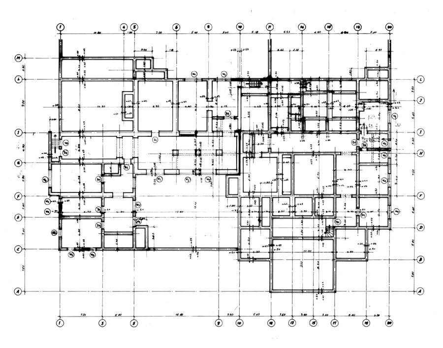
44. Technical Drawings
Technical drawings are a general term encompassing all types of precise drawings used to convey technical or engineering information about an object, product, system or structure through illustrations, dimensions, notes, symbols, and conventions.

To get professional advice and assistance on your construction projects, contact us at Monarch Innovation for our host of BIM, Building Design, and Mechanical Engineering services.
Backed up by experience in this field, we would be happy to help you get insights, and in-depth analysis, and coordinate your project plans to make the process hassle-free.
FAQs
What are construction drawings?
Construction Drawings are a graphical representation of what will be built, how it will be laid out, the components, framework, and dimensions. There is a construction drawing highlighting the details of every aspect of a construction project.
What are the different types of construction drawings?
Below is the set of basic drawings included in the Construction drawings:
1. Elevation drawings – These drawings offer an overview of the individual components that make up the structure, plus the structure as a whole.
2. Sections – Sections are slices of the building, to showcase the inner dimensions.
3. Floor Plans – The rendering of each of the floors in a building, which lays out the rooms, the doors, the positioning of the stairs, windows, columns, kitchen, slabs, etc all in 1D. It helps one to understand the orientation of the rooms and other physical structures that make up the floor.
4. Details – As the name suggests, these are drawings that focus more on individual components of a building, in detail.
What are architectural construction drawings?
Architectural Construction Drawings are drawing work that is used in building drawings to depict the dimensions, depth, and layout of the actual building, before beginning the construction. Architectural Drawings act as a blueprint construction, drawn to scale, to help the engineers visualize the project.
How to make construction drawings?
Construction drawings usually include a set of working drawings that cover different aspects of the project plan. These drawings usually comprise Elevation drawings, Floor Plans, Sections, and Detail Drawings.

